- Messages
- 66
- Reaction score
- 17
- Points
- 18
Please avoid discussing until after 24 hours....
🚀 NEW from the xtremepape.rs team: AI exam prep — 150,000+ worked solutions, and it marks your handwritten working from a photo. Sign in with your forum account & try it free → prepare.xtremepape.rs


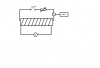
Diagram for question 1 :
Aoa! are you sure this the correct diagram??
I too made the same, except that i connected the CRO with AC supply n I didnt add the variable resistor...

My gradient was 4500 with powers of -6 or -7 ! :s can't remember ! =/
Btw, the independent variable was current, I and dependent variable was frequency, f !

I guess the independent was frequency and the dependent was current. The question clearly mentions it.
I guess the independent was frequency and the dependent was current. The question clearly mentions it.
:O
what was kept constant ?
and what about the diagram ?
:O
what was kept constant ?
and what about the diagram ?
I kept the no. of turns in the coil and the current from the power supply constant and used a variable frequency generator to vary the frequency.


How can you kept the current constant ? :O
didnt we have to use type of signal generator ?
? There was no reason for its use, I suppose.
didnt we have to use type of signal generator ?
Its simple. Use a rheostat and an ammeter. That's all !
🚀 NEW from the xtremepape.rs team: AI exam prep — 150,000+ worked solutions, and it marks your handwritten working from a photo. Sign in with your forum account & try it free → prepare.xtremepape.rs