-
Prepare by Xtremepapers!
🚀 NEW from the xtremepape.rs team: AI exam prep — 120,000+ worked solutions, and it marks your handwritten working from a photo. Sign in with your forum account & try it free → prepare.xtremepape.rs
You are using an out of date browser. It may not display this or other websites correctly.
You should upgrade or use an alternative browser.
You should upgrade or use an alternative browser.
physics help needed on basic electronic principles
- Thread starter eyamwir
- Start date
- Messages
- 97
- Reaction score
- 23
- Points
- 8
For the first file
(a) for the parallel circuit it is 1/20 +1/20=1/10 So inverse that and you get 10 ohm. So total resistance is 20 ohm
(b) voltage drop means change of voltage from one end of the resistor to the other.Since total R is 20 ohm, and there's equally 10 ohm and 10 ohm(parallel circuit), division of voltage should be equal. Think potential divider. From the battery, 20 V will flow and enter the first 10 ohm resistor. So 10 V is used up in the first resistor. This is drop of 10 V. When current travels into parallel circuit, volt across the 15 and 5 ohm will be equal to the volt across the 20 ohm resistor. So voltage drop is still 10 V whether it is across the 15 and 5 ohm OR the 20 ohm resistor. When current travels back to the battery, all the 20 V would be used up already.
(c) you can use P=VI or P=I2R or P=V2/R Since we know the V and the R, we should use P=V2/R.
Total volt across 15 AND 5 ohm=10V
V across 5 ohm resistor = 5/20 x 10V
= 2.5V
P= (2.5)squared / 5
= 1.25W
(d) I=V/R
= 20/20 (total R from (a))
= 1 A
At the parallel circuit, 1A split into two junction. Both junctions have R of 20 ohm. So division of current is equal, 0.5 A.
For second file
P=VI
I= 72/24=3A
3A split into 15 ohm and 20 ohm
I would use ratio here.
15/35 x 3= 1.3A (this is current across the 20 ohm NOT 15 ohm)
20/35 x 3= 1.7A (this is current across the 15 ohm)
Current can flow more through a weaker resistor. So the bigger ratio of the current, 1.7 A will flow through the 15 ohm while the 1.3 A will flow through the 20 ohm resistor.
This is where I can solve up to because according to my calculations, total resistance across the parallel circuit is 8.5 ohm but total power=V2/R shows that total R in the circuit is 8 nohm only. You might need to ask another person.
I'll post solutions to the third one later.
thank youFor the first file
(a) for the parallel circuit it is 1/20 +1/20=1/10 So inverse that and you get 10 ohm. So total resistance is 20 ohm
(b) voltage drop means change of voltage from one end of the resistor to the other.Since total R is 20 ohm, and there's equally 10 ohm and 10 ohm(parallel circuit), division of voltage should be equal. Think potential divider. From the battery, 20 V will flow and enter the first 10 ohm resistor. So 10 V is used up in the first resistor. This is drop of 10 V. When current travels into parallel circuit, volt across the 15 and 5 ohm will be equal to the volt across the 20 ohm resistor. So voltage drop is still 10 V whether it is across the 15 and 5 ohm OR the 20 ohm resistor. When current travels back to the battery, all the 20 V would be used up already.
(c) you can use P=VI or P=I2R or P=V2/R Since we know the V and the R, we should use P=V2/R.
Total volt across 15 AND 5 ohm=10V
V across 5 ohm resistor = 5/20 x 10V
= 2.5V
P= (2.5)squared / 5
= 1.25W
(d) I=V/R
= 20/20 (total R from (a))
= 1 A
At the parallel circuit, 1A split into two junction. Both junctions have R of 20 ohm. So division of current is equal, 0.5 A.
For second file
P=VI
I= 72/24=3A
3A split into 15 ohm and 20 ohm
I would use ratio here.
15/35 x 3= 1.3A (this is current across the 20 ohm NOT 15 ohm)
20/35 x 3= 1.7A (this is current across the 15 ohm)
Current can flow more through a weaker resistor. So the bigger ratio of the current, 1.7 A will flow through the 15 ohm while the 1.3 A will flow through the 20 ohm resistor.
This is where I can solve up to because according to my calculations, total resistance across the parallel circuit is 8.5 ohm but total power=V2/R shows that total R in the circuit is 8 nohm only. You might need to ask another person.
I'll post solutions to the third one later.
") i'll be waiting for the third and fourth qs
i'll be waiting for the third and fourth qs 
- Messages
- 97
- Reaction score
- 23
- Points
- 8
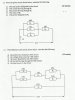
For third question:
(a) P : VI
=40 x 3=120 W
(b) (c)(d)Total R of circuit: V/I: 13.33 ohmn
13.33- 10= 3.33 ohm (total R for parallel circuit)
1/20 + 1/ 5+ 1/R3= 1/3.33
R3= 20 ohm (Had to solve this first to find current split into each resistor)
Using potential divider theory,
3.33/13.33 x 40 = 10V( across parallel circuits)
For I1(across R1)= V/R1 = 10/20= 0.5A
For I2(across R2)= 10/5= 2.0A
For I3 (across R3) = 10/20= 0.5A
You should find that I1 +I2+I3 = 3.0A
(e) P=I2R
= (3)squared x 10 =90 W
Fourth question:
(a) From top circuit,
1/20+1/10=3/20 R= 1/(3/20)= 6.67 ohm
Second parallel:
1/30+1/40=7/120 R=17.1 ohm
Total R at top circuit= 6.67+ 17.1+ 15=38.8 ohm
Total R of Circuit= 1/38.8 +1/25=0.0658
1/0.0658= 15.2 ohm
(b) 15/38.8 x 150 = 58.0 V voltage across parallel circuit is equal and I used potential divider theory here.
(c) Voltage across first upper left parallel circuit = 6.67/38.8 x 150 =25.8V This voltage is equal for 20 ohm resistor and 10 ohm resistor.
P=V2/R= 25.8(squared)/ 20=33.2W
(d) V across parallel circuit on upper right = 17.1/38.8 x 150=66.1 V
I= V/R= 66.1/40=1.65A
(e) P=V2/R
= 150(squared) / 15.2
= 1480 W
For question 4, I used 3 s.f. so it might not be very accurate, depending on the answer scheme, if they used calculator values. I'm completely confident of my answers so make sure you check with the answer or your teacher. Are you doing AS level now? Taking the Oct/Nov exam?
nope. i already did my A levels in 2011. i'm currently doing my college diploma in process/plant engineering. and sadly there's this module on basic electronics principle which is unfortunate because i never actually done physics in A level :s that's why i'm in need of help. and this qs is a part of my assignment :// anyway thank you for your help :3 except that...i don't really get the same answer as yours in question 2
- Messages
- 97
- Reaction score
- 23
- Points
- 8
I see. Physics in A-level is useful huh? Anyway, potential divider is used to divide supply voltage into values required in individual resistors. It has a formula, not really a theory(haha, called it theory as in understanding of the formula and how it works).
V of a certain resistor= Value of resistor/ Value of total resistance x total voltage supply
So if voltage supply was 10V, there's a 2 ohm and 5 ohm resistor in series and you wanna find voltage across the 5 ohm...
V= 5/ (2+5) x 10 = 7.1 V
If it was across 2 ohm you want....
V= 2/ (2+5) x 10 = 2.9 V
When you add them up, they should have total 10 V.
It's really convenient, potential divider. For more understanding, go here http://www.revisesmart.co.uk/physics/sensing/potential-dividers.html
They have simple explanation so you can understand just the basic of it. But best you learn this. Its handy
Oh, can you tell me what's different in my answer and yours in question 2? I might have done it wrong with all this typing
- Messages
- 97
- Reaction score
- 23
- Points
- 8
You need to find current that splits into the first junction(into the first parallel set and the 25 ohm resistor). Then use V=IR to find voltagei have another question how do you solve qs 4 in alternative method which is by not using potential divider theory
about the qs 2 i just got informed by my tutor that the power was wrongly typed -.-' it was supposed to be 7.2 watts...
and i tried solving according to your steps and it seems that the total current is 0.3A and when i solved the current for I1 and I2 it was 0.13A and 0.17A and the resistance for Rx was 80 ohms which was...a big value or was it...i was wrong?
originally i did qs 2 using ohm's law in which the current i got was 1.2A and 1.6A which was a difference of 0.1A to your answer...can you double check?
- Messages
- 97
- Reaction score
- 23
- Points
- 8
about the qs 2 i just got informed by my tutor that the power was wrongly typed -.-' it was supposed to be 7.2 watts...
and i tried solving according to your steps and it seems that the total current is 0.3A and when i solved the current for I1 and I2 it was 0.13A and 0.17A and the resistance for Rx was 80 ohms which was...a big value or was it...i was wrong?
originally i did qs 2 using ohm's law in which the current i got was 1.2A and 1.6A which was a difference of 0.1A to your answer...can you double check?
okay, if the power is 7.2 W means current is 0.3A. I1 and I2 should be 0.13 and 0.17A. V=IR means total R of circuit is 80 ohm. Across the parallel circuit, total R is 1/20 +1/15=7/60. Inverse that and R = 8.6 ohm. So Rx = Total R of circuit - R of parallel circuit= 71.4 ohm. That should be the answer
The resistance isn't too big for the whole circuit but 71.4 ohm might seem big for Rx only.- Messages
- 97
- Reaction score
- 23
- Points
- 8
you're welcome