- Messages
- 505
- Reaction score
- 739
- Points
- 103
checked the diodes one?ohh k
🚀 NEW from the xtremepape.rs team: AI exam prep — 150,000+ worked solutions, and it marks your handwritten working from a photo. Sign in with your forum account & try it free → prepare.xtremepape.rs
checked the diodes one?ohh k
dint understand....k top of relay coil became positive.....now what happens next......and by the way current shud be damging not an emf....what do u say.....what i am saying is cant it just go into earth if top becomes positive...a..and why after all it will try to damage op-amp as upper end is positive currennt shud move down not up to the op amp......i cant visualise wats happeningD1 is there to avoid any output current from the op amp when the op amp output is at a negative voltage. If the op amp has no negative voltage power supply, then there will be no need for D1.
D2 is there to prevent a high voltage, generated by the coil when power is removed, from damaging the op amp.
When the op amp applies a positive current going down into the coil, a current is flowing in the coil. This current generates a magnetic field around the coil and core. If the op amp output suddenly switches off (i.e. goes to zero volts, or goes negative), then the magnetic field will start to collapse at a high rate. As the magnetic lines of flux fall back through the coil windings as the field collapses, a voltage is developed across the coil. The voltage is such that the top end of the coil (at the op amp) will go to a positive voltage. Without D2, this voltage can go high enough so that the op amp can be damaged. Diode D2 shunts the current to ground so that the voltage can't go higher than about 1 volt. This also allows some current to continue to flow in the coil as the magnetic field decays, which also allows the voltage that would be developed by the coil to be reduced. This also makes it take a few more milliseconds for the relay to finish its mechanical movement.
Source:- http://en.allexperts.com/q/Electrical-Engineering-1356/2011/4/Protection-Diode-Relay.htm
The second diagram is the answer to that question you asked..that box thing below the diode is the coilGUys tis is like a simple circuit of relay...? where is the coil for induction...?
angel girl u told it the best waythanx alot fr Ur response i understood question 7. thanx alot.
fr question 3 u reached the final answer correctly, yes it is upwards but the method u used is too time consuming and alittle bit tricky too.
isn't it the simple use of sinosidal graph??? to predict the direction wid use of angle??

dont go in this much depth just remember a relay stop high currents by small currents that is itThe second diagram is the answer to that question you asked..that box thing below the diode is the coil

anyyy 11??????dint understand....k top of relay coil became positive.....now what happens next......and by the way current shud be damging not an emf....what do u say.....what i am saying is cant it just go into earth if top becomes positive...a..and why after all it will try to damage op-amp as upper end is positive currennt shud move down not up to the op amp......i cant visualise wats happening
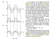
ikr...luv that sitefinally got it.....half wave rectification curves!!!
i forgot to say its cosine graph and yes it does start with a maximum value hence piston is 120 degree lagging behind but will be in same direction as the max displacement wasthanx alot fr Ur response i understood question 7. thanx alot.
fr question 3 u reached the final answer correctly, yes it is upwards but the method u used is too time consuming and alittle bit tricky too.
isn't it the simple use of sinosidal graph??? to predict the direction wid use of angle??
does thatt mean the graphs i drew here are wronganyyy 11??????
: http://www.xtremepapers.com/communi...st-your-doubts-here.13317/page-37#post-231952what was that attachmentnoooo they are correct ....m asking for the relay cnfusion
June 2002 Question 6 a) did you find the answer? Please post a pic of it, and I will reply if I agree.

so do I...This is what i think is right
This is what i think is right View attachment 9365
yes i think so too. We need more confirmations from more ppl !so do I...
haha..then it's correctyes i think so too. We need more confirmations from more ppl !
why shudn't they be at the same side...the output produced is the same right? as the input varies + to - and - to + , the diodes that work change...2 of them will be working in the first case, and the other two in the second...but bot h produce the same output..!well @user....why graphs for thos diodes are 2wards the same side
Ill just pretend, i didnt see that... haha jokingwhat was that attachment

congragulations but you wont be using them in the exam hahafinally got it.....half wave rectification curves!!!
🚀 NEW from the xtremepape.rs team: AI exam prep — 150,000+ worked solutions, and it marks your handwritten working from a photo. Sign in with your forum account & try it free → prepare.xtremepape.rs