- Messages
- 23
- Reaction score
- 38
- Points
- 13
how would you enter 2sinw15 into the calc.Gimme that question in which you got a problem.
🚀 NEW from the xtremepape.rs team: AI exam prep — 150,000+ worked solutions, and it marks your handwritten working from a photo. Sign in with your forum account & try it free → prepare.xtremepape.rs
how would you enter 2sinw15 into the calc.Gimme that question in which you got a problem.
1) - 4 b (iv):
1. Applying Kirchoff's Law, we get the value of the current to be 0.24 Amperes. So, the potential difference across a resistor with resistance R and current I flowing
through it is given by
P.D. = IV = 0.24 * 5.5 = 1.32 Volts. (However, since this is a drop, the change in potential should be -1.32 Volts)
2. The terminal P.D. across any cell is the Potential Difference across it's terminals, and this includes not only the cells that convert chemical energy to electric
potential energy, but the internal resistance. So, the terminal P.D. across cell A is the algebraic sum of the potential changes that occur as you go from end to end.
In other words, you start from the right side, this side being defined as the negative terminal of the battery, and you move across the battery. There are two
potential changes here - the drop across the internal resistance, and the increase across the cells.
So the potential drop across the internal resistance of Battery A = 0.24 * 2.3 = 0.55 Volts. Since this is a decrease in potential, we write it as -0.55 V.
In addition, the potential rise across the cells of Battery A = 4.4 Volts since that is the emf of the collection of cells. Since this is a rise in potential, we write it as
+4.4 V.
Adding these up, we get 4.4 - 0.55 = 3.848 = 3.85 Volts.
3. For this, we return to Kirchoff's Law, and we input our values. The equation from my page is
-2.3I + 4.4 - 2.1 - 1.8I - 5.5I = 0
Alternatively, this can be written as (Potential change across Battery A) + (Potential Change across Battery B) + (Potential change across Resistor R) = 0
From what we have calculated so far, we can write (3.85 Volts) + (Potential Change across Battery B) + (1.32 Volts) = 0
However, the one issue with this equation is that since the current is going from the positive terminal of Battery B to the negative terminal of battery B, the potential difference given by this equation will be (Potential of negative terminal) - (Potential of positive terminal).
By definition, this is the negative of the terminal PD, so while the value we get is -2.53 Volts, the terminal PD itself is 2.53 Volts.
2) 4 b (iii)
From the earlier part of the question, you will have obtained the value of 7 * 10^5 slits per meter. It can be assumed that this is the same value to be used in the next part, so we continue as follows:
Part b(ii) is talking about light of wavelength 625 nm, passing through the diffraction grating with (7 * 10^5) slits per meter, that has a second order maxima at an angle of 61.0° to the straight-through direction.
Part b(iii) wants us to find the wavelength of light that passes through a diffraction grating with (7 * 10^5) slits per meter, that has a maxima of some other order at 61.0° to the straight-through direction. So, we replace n = 2 in the previous question with either 1, or 3, or 4, etc.
However, we see first that the wavelength of line concerned should be in the visible part of the spectrum (this part ranges from about 400 nm to 800 nm) , and in the equation
nλ = dsin(61.0)
the right side is constant; the number of slits per meter (and therefore the distance between slits) is constant in both equations, and the sine function is also constant, since the angle remains the same in both situations.
Therefore, the value of nλ from the previous question is the same as that used here. So, since n was 2 in b(ii) and λ was 625 nm, we can write
1250 nm = nλ(2)
Supposing we put n = 1, we get λ = 1250 nm. This is not is the range of visible light, so we have to discard this.
Supposing we put n = 3, we get λ = 417 nm. This is indeed in the visible spectrum.
Supposing we put n =4, we get λ = 312.5 nm, which is too low to be visible.
So, our answer is 417 nm, since this is the only possible wavelength for which light with form a maxima at 61.0 degrees to the straight-through direction in these conditions.
I'll try out the rest in some time, just let me know if you've understood these.
Hope this helped!
Good Luck for all your exams!

You mean 2sin15 ?how would you enter 2sinw15 into the calc.
P3 means, Practical papers :/hmmm.... m nt prepared for S1 at all :/
P1 means MCQ paper..P3 means, Practical papers :/
ohhh... i was thinkng abt maths...P3 means, Practical papers :/
hmm.. :/ Ok.ohhh... i was thinkng abt maths...
P1 will be tricky... n for P3 u need practice
Dw percentiles are low tooI know we have time... but, shii man! :
Bro i solved your question below..
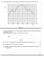
Bro its smthg like this for the sketch part u need to combine both......What i mean here is u need to subtract numerical values..Initially the graph need tobe almost same as ea because ep very small...Then around 12 it will pass x axis...Hope u get it....Anyone can help with this question guys....
As far as I understand u mean that I will take value of electric field strength on both graph and their difference will be the point from where my graph will pass!thanksBro its smthg like this for the sketch part u need to combine both......What i mean here is u need to subtract numerical values..Initially the graph need tobe almost same as ea because ep very small...Then around 12 it will pass x axis...Hope u get it....
Sorry bro not good at direct sensing,if it comes in exam all I know is that I am gonna put a resistor and a Thermistor in series a draw a voltmeter in parallel to the thermistor,now I don't know the temperature thingy in the question so got no logic to that!Guys need a help.Can anyone help me?Thanks in advance!!!!
Nvr mind man.Thanks a lot!!!!Sorry bro not good at direct sensing,if it comes in exam all I know is that I am gonna put a resistor and a Thermistor in series a draw a voltmeter in parallel to the thermistor,now I don't know the temperature thingy in the question so got no logic to that!
Imagine the graph of the output by looking at the binary values u have calculated it will be like this as in the attachment,as u see there the graph has large steps thus frequency in inadequate.when the graph will have small height freq ok,if graph base is small see attachment then means no of bits taken are okayGuys can anyone help me with this question part c.Just dont get what they say....The answer is
significant changes in detail of V between samplings so frequency too low,....Thanks alot guys!!!
Thanks a lot brother!!Imagine the graph of the output by looking at the binary values u have calculated it will be like this as in the attachment,as u see there the graph has large steps thus frequency in inadequate.when the graph will have small height freq ok,if graph base is small see attachment then means no of bits taken are okay
🚀 NEW from the xtremepape.rs team: AI exam prep — 150,000+ worked solutions, and it marks your handwritten working from a photo. Sign in with your forum account & try it free → prepare.xtremepape.rs